Stereo matching module
The stereo matching module is a base module which is available on every rc_cube and uses the rectified stereo-image pair to compute disparity, error, and confidence images.
Note
This module is not available in camera pipelines of type zivid, orbbec or blaze.
To compute full resolution disparity, error and confidence images, an additional StereoPlus license is required. This license is included in every rc_cube purchased after 31.01.2019.
Parameters
The stereo matching module is called rc_stereomatching in the REST-API and it is represented by the
Depth Image page in the desired pipeline in the Web GUI.
The user can change the stereo matching parameters there, or use the REST-API
(REST-API interface).
Parameter overview
This module offers the following run-time parameters:
| Name | Type | Min | Max | Default | Description |
|---|---|---|---|---|---|
acquisition_mode |
string | - | - | Continuous | Acquisition mode: [Continuous, SingleFrame, SingleFrameOut1] |
double_shot |
bool | false | true | false | Combination of disparity images from two subsequent stereo image pairs |
exposure_adapt_timeout |
float64 | 0.0 | 2.0 | 0.0 | Maximum time in seconds to wait after triggering in SingleFrame modes until auto exposure has finished adjustments |
fill |
int32 | 0 | 4 | 3 | Disparity tolerance for hole filling in pixels |
maxdepth |
float64 | 0.1 | 100.0 | 100.0 | Maximum depth in meters |
maxdeptherr |
float64 | 0.01 | 100.0 | 100.0 | Maximum depth error in meters |
minconf |
float64 | 0.5 | 1.0 | 0.5 | Minimum confidence |
mindepth |
float64 | 0.1 | 100.0 | 0.1 | Minimum depth in meters |
quality |
string | - | - | High | Quality: [Low, Medium, High, Full]. Full requires ‘stereo_plus’ license. |
roi_height |
int32 | 0 | 960 | 0 | Height of region of interest. 0 for whole image. |
roi_offset_x |
int32 | 0 | 1280 | 0 | First column of region of interest |
roi_offset_y |
int32 | 0 | 960 | 0 | First row of region of interest |
roi_width |
int32 | 0 | 1280 | 0 | Width of region of interest. 0 for whole image. |
seg |
int32 | 0 | 4000 | 200 | Minimum size of valid disparity segments in pixels |
smooth |
bool | false | true | true | Smoothing of disparity image (requires ‘stereo_plus’ license) |
static_scene |
bool | false | true | false | Accumulation of images in static scenes to reduce noise |
These parameters are also available over the GenICam interface with slightly different names and partly with different data types (see GigE Vision 2.0/GenICam image interface).
Description of run-time parameters
Each run-time parameter is represented by a row on the Web GUI’s Depth Image page. The name in the Web GUI is given in brackets behind the parameter name and the parameters are listed in the order they appear in the Web GUI:
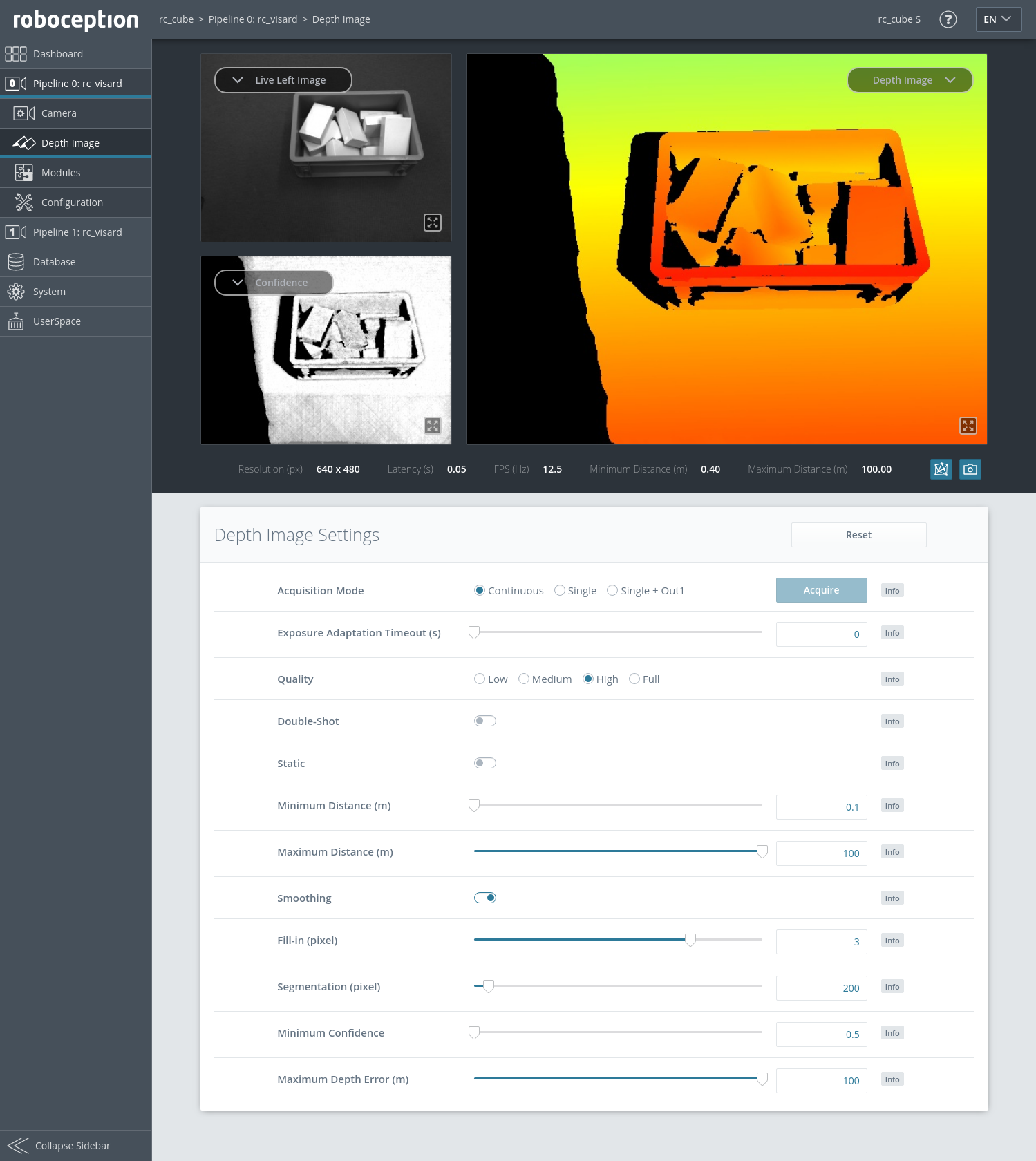
Fig. 10 The Web GUI’s Depth Image page
acquisition_mode (Acquisition Mode)
The acquisition mode can be set to
Continuous,SingleFrame(Single) orSingleFrameOut1(Single + Out1). The first one is the default, which performs stereo matching continuously according to the user defined frame rate and the available computation resources. The two other modes perform stereo matching upon each click of the Acquire button. The Single + Out1 mode additionally controls an external projector that is connected to GPIO Out1 (IO and Projector Control). In this mode,out1_modeof the IOControl module is automatically set toExposureAlternateActiveupon each trigger call and reset toLowafter receiving images for stereo matching.Note
The
Single + Out1mode can only change theout1_modeif the IOControl license is available on the rc_cube.Via the REST-API, this parameter can be set as follows.
PUT http://<host>/api/v2/pipelines/<0,1,2,3>/nodes/rc_stereomatching/parameters?acquisition_mode=<value>PUT http://<host>/api/v1/nodes/rc_stereomatching/parameters?acquisition_mode=<value>
exposure_adapt_timeout (Exposure Adaptation Timeout)
The exposure adaptation timeout gives the maximum time in seconds that the system will wait after triggering an image acquisition until auto exposure has found the optimal exposure time. This timeout is only used in
SingleFrame(Single) orSingleFrameOut1(Single + Out1) acquisition mode with auto exposure active. This value should be increased in applications with changing lighting conditions, when images are under- oder overexposed and the resulting disparity images are too sparse. In these cases multiple images are acquired until the auto-exposure mode has adjusted or the timeout is reached, and only then the actual image acquisition is triggered.Via the REST-API, this parameter can be set as follows.
PUT http://<host>/api/v2/pipelines/<0,1,2,3>/nodes/rc_stereomatching/parameters?exposure_adapt_timeout=<value>PUT http://<host>/api/v1/nodes/rc_stereomatching/parameters?exposure_adapt_timeout=<value>
quality (Quality)
Disparity images can be computed in different resolutions:
Full(full image resolution),High(half of the full image resolution),Medium(quarter of the full image resolution) andLow(sixth of the full image resolution). Full resolution matching (Full) is only possible with a valid StereoPlus license. The lower the resolution, the higher the frame rate of the disparity image. Please note that the frame rate of the disparity, confidence, and error images will always be less than or equal to the camera frame rate. In case the projector is inExposureAlternateActivemode, the frame rate of the images can be at most half of the camera frame rate.If full resolution is selected, the depth range is internally limited due to limited on-board memory resources. It is recommended to adjust
mindepthandmaxdepthto the depth range that is required by the application.
Table 13 Depth image resolutions (pixel) depending on the chosen quality¶ Connected Camera Full Quality High Quality Medium Quality Low Quality rc_visard 1280 x 960 640 x 480 320 x 240 214 x 160 rc_visard_ng 1440 x 1080 720 x 540 360 x 270 240 x 180 rc_viscore 4112 x 3008 2056 x 1504 1028 x 752 686 x 502 Via the REST-API, this parameter can be set as follows.
PUT http://<host>/api/v2/pipelines/<0,1,2,3>/nodes/rc_stereomatching/parameters?quality=<value>PUT http://<host>/api/v1/nodes/rc_stereomatching/parameters?quality=<value>
roi_offset_x, roi_offset_y, roi_width, roi_height (Stereo ROI)
These values define a rectangular region in the left rectified image for limiting the area used for computing the depth values. This reduces the stereo matching run time and, thus, the latency. If either the width or height is 0, then the whole left and right images are used for stereo matching. By default, all values are 0.
The stereo ROI is visualized in the Web GUI by a white overlay of the unused image area in the left rectified image. It can be defined using the sliders or by selecting it in the image after pressing the button
Stereo Region of Interest.Via the REST-API, these parameters can be set as follows.
PUT http://<host>/api/v2/pipelines/<0,1,2,3>/nodes/rc_stereomatching/parameters?<roi_offset_x|roi_offset_y|roi_width|roi_height>=<value>PUT http://<host>/api/v1/nodes/rc_stereomatching/parameters?<roi_offset_x|roi_offset_y|roi_width|roi_height>=<value>
mindepth (Minimum Distance)
The minimum distance is the smallest distance from the camera at which measurements should be possible. Larger values implicitly reduce the disparity range, which also reduces the computation time. The minimum distance is given in meters.
Depending on the capabilities of the sensor, the actual minimum distance can be higher than the user setting. The actual minimum distance will be reported in the status values.
Via the REST-API, this parameter can be set as follows.
PUT http://<host>/api/v2/pipelines/<0,1,2,3>/nodes/rc_stereomatching/parameters?mindepth=<value>PUT http://<host>/api/v1/nodes/rc_stereomatching/parameters?mindepth=<value>
maxdepth (Maximum Distance)
The maximum distance is the largest distance from the camera at which measurements should be possible. Pixels with larger distance values are set to invalid in the disparity image. Setting this value to its maximum permits values up to infinity. The maximum distance is given in meters.
Via the REST-API, this parameter can be set as follows.
PUT http://<host>/api/v2/pipelines/<0,1,2,3>/nodes/rc_stereomatching/parameters?maxdepth=<value>PUT http://<host>/api/v1/nodes/rc_stereomatching/parameters?maxdepth=<value>
double_shot (Double-Shot)
Enabling this option will lead to denser disparity images, but will increase processing time.
For scenes recorded with a projector in
Single + Out1acquisition mode, or in continuous acquisition mode with the projector inExposureAlternateActivemode, holes caused by reflections of the projector are filled with depth information computed from the images without projector pattern. In this case, thedouble_shotparameter must only be enabled if the scene does not change during the acquisition of the images.For all other scenes, holes are filled with depth information computed from a downscaled version of the same image.
Via the REST-API, this parameter can be set as follows.
PUT http://<host>/api/v2/pipelines/<0,1,2,3>/nodes/rc_stereomatching/parameters?double_shot=<value>PUT http://<host>/api/v1/nodes/rc_stereomatching/parameters?double_shot=<value>
static_scene (Static)
This option averages 8 consecutive camera images before matching. This reduces noise, which improves the stereo matching result. However, the latency increases significantly. The timestamp of the first image is taken as timestamp of the disparity image. This option only affects matching in full or high quality. It must only be enabled if the scene does not change during the acquisition of the 8 images.
Via the REST-API, this parameter can be set as follows.
PUT http://<host>/api/v2/pipelines/<0,1,2,3>/nodes/rc_stereomatching/parameters?static_scene=<value>PUT http://<host>/api/v1/nodes/rc_stereomatching/parameters?static_scene=<value>
smooth (Smoothing)
This option activates advanced smoothing of disparity values. It is only available with a valid StereoPlus license.
Via the REST-API, this parameter can be set as follows.
PUT http://<host>/api/v2/pipelines/<0,1,2,3>/nodes/rc_stereomatching/parameters?smooth=<value>PUT http://<host>/api/v1/nodes/rc_stereomatching/parameters?smooth=<value>
fill (Fill-in)
This option is used to fill holes in the disparity image by interpolation. The fill-in value is the maximum allowed disparity step on the border of the hole. Larger fill-in values can decrease the number of holes, but the interpolated values can have larger errors. At most 5% of pixels are interpolated. Interpolation of small holes is preferred over interpolation of larger holes. The confidence for the interpolated pixels is set to a low value of 0.5. A fill-in value of 0 switches hole filling off.
Via the REST-API, this parameter can be set as follows.
PUT http://<host>/api/v2/pipelines/<0,1,2,3>/nodes/rc_stereomatching/parameters?fill=<value>PUT http://<host>/api/v1/nodes/rc_stereomatching/parameters?fill=<value>
seg (Segmentation)
The segmentation parameter is used to set the minimum number of pixels that a connected disparity region in the disparity image must fill. Isolated regions that are smaller are set to invalid in the disparity image. The value is related to the high quality disparity image with half resolution and does not have to be scaled when a different quality is chosen. Segmentation is useful for removing erroneous disparities. However, larger values may also remove real objects.
Via the REST-API, this parameter can be set as follows.
PUT http://<host>/api/v2/pipelines/<0,1,2,3>/nodes/rc_stereomatching/parameters?seg=<value>PUT http://<host>/api/v1/nodes/rc_stereomatching/parameters?seg=<value>
minconf (Minimum Confidence)
The minimum confidence can be set to filter potentially false disparity measurements. All pixels with less confidence than the chosen value are set to invalid in the disparity image.
Via the REST-API, this parameter can be set as follows.
PUT http://<host>/api/v2/pipelines/<0,1,2,3>/nodes/rc_stereomatching/parameters?minconf=<value>PUT http://<host>/api/v1/nodes/rc_stereomatching/parameters?minconf=<value>
maxdeptherr (Maximum Depth Error)
The maximum depth error is used to filter measurements that are too inaccurate. All pixels with a larger depth error than the chosen value are set to invalid in the disparity image. The maximum depth error is given in meters. The depth error generally grows quadratically with an object’s distance from the camera (see Confidence and error images).
Via the REST-API, this parameter can be set as follows.
PUT http://<host>/api/v2/pipelines/<0,1,2,3>/nodes/rc_stereomatching/parameters?maxdeptherr=<value>PUT http://<host>/api/v1/nodes/rc_stereomatching/parameters?maxdeptherr=<value>
Status values
This module reports the following status values:
| Name | Description |
|---|---|
fps |
Actual frame rate of the disparity, error, and confidence images. This value is shown in the Web GUI below the image preview as FPS (Hz). |
latency |
Time in seconds between image acquisition and publishing of disparity image. This value is shown in the Web GUI below the image preview as Latency (s). |
width |
Current width of the disparity, error, and confidence images in pixels. This value is shown in the Web GUI below the image preview as the first number of Resolution (px). |
height |
Current height of the disparity, error, and confidence images in pixels. This value is shown in the Web GUI below the image preview as the second number of Resolution (px). |
mindepth |
Actual minimum working distance in meters. This value is shown in the Web GUI below the image preview as Minimum Distance (m). |
maxdepth |
Actual maximum working distance in meters. This value is shown in the Web GUI below the image preview as Maximum Distance (m). |
time_matching |
Time in seconds for performing stereo matching using SGM on the GPU |
time_postprocessing |
Time in seconds for postprocessing the matching result on the CPU |
reduced_depth_range |
Indicates whether the depth range is reduced due to computation resources |
Services
The stereo matching module offers the following services.
acquisition_trigger
Signals the module to perform stereo matching of the next available images, if the parameter
acquisition_modeis set toSingleFrameorSingleFrameOut1.Details
An error is returned if the
acquisition_modeis set toContinuous.This service can be called as follows.
PUT http://<host>/api/v2/pipelines/<0,1,2,3>/nodes/rc_stereomatching/services/acquisition_triggerPUT http://<host>/api/v1/nodes/rc_stereomatching/services/acquisition_triggerThis service has no arguments.Possible return codes are shown below.
Table 15 Possible return codes of the acquisition_triggerservice call.¶Code Description 0 Success -8 Triggering is only possible in SingleFrame acquisition mode 101 Trigger is ignored, because there is a trigger call pending 102 Trigger is ignored, because there are no subscribers The definition for the response with corresponding datatypes is:
{
  "name": "acquisition_trigger",
  "response": {
    "return_code": {
      "message": "string",
      "value": "int16"
    }
  }
}
reset_defaults
Restores and applies the default values for this module’s parameters (“factory reset”).
Details
This service can be called as follows.
PUT http://<host>/api/v2/pipelines/<0,1,2,3>/nodes/rc_stereomatching/services/reset_defaultsPUT http://<host>/api/v1/nodes/rc_stereomatching/services/reset_defaultsThis service has no arguments.The definition for the response with corresponding datatypes is:
{
  "name": "reset_defaults",
  "response": {
    "return_code": {
      "message": "string",
      "value": "int16"
    }
  }
}