Stereo matching
The stereo matching module is a base module which is available on every rc_cube and uses the rectified stereo-image pair to compute disparity, error, and confidence images.
To compute full resolution disparity, error and confidence images, an additional StereoPlus license is required. This license is included in every rc_cube purchased after 31.01.2019.
Computing disparity images
After rectification, an object point is guaranteed to be projected onto the same pixel row in both left and right image. That point’s pixel column in the right image is always lower than or equal to the same point’s pixel column in the left image. The term disparity signifies the difference between the pixel columns in the right and left images and expresses the depth or distance of the object point from the camera. The disparity image stores the disparity values of all pixels in the left camera image.
The larger the disparity, the closer the object point. A disparity of 0 means that the projections of the object point are in the same image column and the object point is at infinite distance. Often, there are pixels for which disparity cannot be determined. This is the case for occlusions that appear on the left sides of objects, because these areas are not seen from the right camera. Furthermore, disparity cannot be determined for textureless areas. Pixels for which the disparity cannot be determined are marked as invalid with the special disparity value of 0. To distinguish between invalid disparity measurements and disparity measurements of 0 for objects that are infinitely far away, the disparity value for the latter is set to the smallest possible disparity value above 0.
To compute disparity values, the stereo matching algorithm has to find corresponding object points in the left and right camera images. These are points that represent the same object point in the scene. For stereo matching, the rc_cube uses SGM (Semi-Global Matching), which offers quick run times and great accuracy, especially at object borders, fine structures, and in weakly textured areas.
A key requirement for any stereo matching method is the presence of texture in the image, i.e., image-intensity changes due to patterns or surface structure within the scene. In completely untextured regions such as a flat white wall without any structure, disparity values can either not be computed or the results are erroneous or have low confidence (see Confidence and error images). The texture in the scene should not be an artificial, repetitive pattern, since those structures may lead to ambiguities and hence to wrong disparity measurements.
When working with poorly textured objects or in untextured environments, a static artificial texture can be projected onto the scene using an external pattern projector. This pattern should be random-like and not contain repetitive structures. The rc_cube provides the IOControl module (see IO and Projector Control) as optional software module which can control a pattern projector connected to the rc_visard.
Computing depth images and point clouds
The following equations show how to compute an object point’s actual 3D coordinates \(P_x, P_y, P_z\) in the camera coordinate frame from the disparity image’s pixel coordinates \(p_{x}, p_{y}\) and the disparity value \(d\) in pixels:
where \(f\) is the focal length after rectification in pixels and \(t\) is the stereo baseline in meters, which was determined during calibration. These values are also transferred over the GenICam interface (see Custom GenICam features of the rc_cube).
Note
The rc_cube reports a focal length factor via its various interfaces. It relates to the image width for supporting different image resolutions. The focal length \(f\) in pixels can be easily obtained by multiplying the focal length factor by the image width in pixels.
Please note that equations (1) assume that the coordinate frame is centered in the principal point that is typically in the center of the image, and \(p_{x}, p_{y}\) refer to the middle of the pixel, i.e. by adding 0.5 to the integer pixel coordinates. The following figure shows the definition of the image coordinate frame.
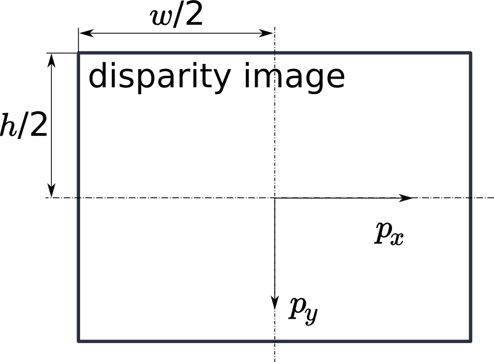
Fig. 7 The image coordinate frame’s origin is defined to be at the image center – \(w\) is the image width and \(h\) is the image height.
The same equations, but with the corresponding GenICam parameters are given in Image stream conversions.
The set of all object points computed from the disparity image gives the point cloud, which can be used for 3D modeling applications. The disparity image is converted into a depth image by replacing the disparity value in each pixel with the value of \(P_z\).
Note
Roboception provides software and examples for receiving disparity images from the rc_cube via GigE Vision and computing depth images and point clouds. See http://www.roboception.com/download.
Confidence and error images
For each disparity image, additionally an error image and a confidence image are provided, which give uncertainty measures for each disparity value. These images have the same resolution and the same frame rate as the disparity image. The error image contains the disparity error \(d_{eps}\) in pixels corresponding to the disparity value at the same image coordinates in the disparity image. The confidence image contains the corresponding confidence value \(c\) between 0 and 1. The confidence is defined as the probability of the true disparity value being within the interval of three times the error around the measured disparity \(d\), i.e., \([d-3d_{eps}, d+3d_{eps}]\). Thus, the disparity image with error and confidence values can be used in applications requiring probabilistic inference. The confidence and error values corresponding to an invalid disparity measurement will be 0.
The disparity error \(d_{eps}\) (in pixels) can be converted to a depth error \(z_{eps}\) (in meters) using the focal length \(f\) (in pixels), the baseline \(t\) (in meters), and the disparity value \(d\) (in pixels) of the same pixel in the disparity image:
Combining equations (1) and (2) allows the depth error to be related to the depth:
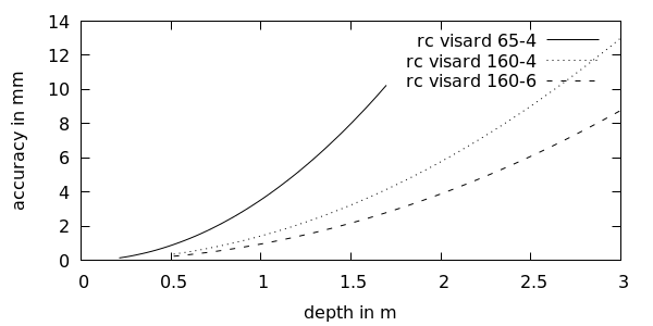
With the focal lengths and baselines of the different rc_visard models and the typical combined calibration and stereo matching error \(d_{eps}\) of 0.25 pixels, the depth accuracy can be visualized as shown below.
Viewing and downloading images and point clouds
The rc_cube provides time-stamped disparity, error, and confidence images over the GenICam interface (see Provided image streams). Live streams of the images are provided with reduced quality in the Web GUI.
The Web GUI also provides the opportunity to download a snapshot of the current scene containing the depth, error and confidence images, as well as a point cloud in ply format as described in Downloading depth images and point clouds.
Parameters
The stereo matching module is called rc_stereomatching in the REST-API and it is represented by the
Depth Image tab in the Web GUI.
The user can change the stereo matching parameters there, or use the REST-API
(REST-API interface) or GigE Vision
(GigE Vision 2.0/GenICam image interface).
Parameter overview
This module offers the following run-time parameters:
| Name | Type | Min | Max | Default | Description |
|---|---|---|---|---|---|
acquisition_mode |
string | - | - | Continuous | Acquisition mode: [Continuous, SingleFrame, SingleFrameOut1] |
double_shot |
bool | false | true | false | Combination of disparity images from two subsequent stereo image pairs |
fill |
int32 | 0 | 4 | 3 | Disparity tolerance for hole filling in pixels |
maxdepth |
float64 | 0.1 | 100.0 | 100.0 | Maximum depth in meters |
maxdeptherr |
float64 | 0.01 | 100.0 | 100.0 | Maximum depth error in meters |
minconf |
float64 | 0.5 | 1.0 | 0.5 | Minimum confidence |
mindepth |
float64 | 0.1 | 100.0 | 0.1 | Minimum depth in meters |
quality |
string | - | - | High | Quality: [Low, Medium, High, Full]. Full requires ‘stereo_plus’ license. |
seg |
int32 | 0 | 4000 | 200 | Minimum size of valid disparity segments in pixels |
smooth |
bool | false | true | true | Smoothing of disparity image (requires ‘stereo_plus’ license) |
static_scene |
bool | false | true | false | Accumulation of images in static scenes to reduce noise |
Description of run-time parameters
Each run-time parameter is represented by a row on the Web GUI’s Depth Image tab. The name in the Web GUI is given in brackets behind the parameter name and the parameters are listed in the order they appear in the Web GUI:
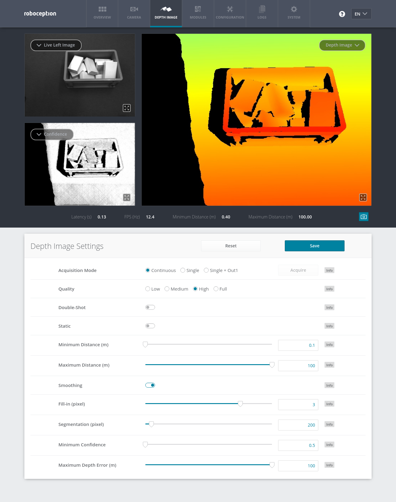
Fig. 8 The Web GUI’s Depth Image tab
acquisition_mode (Acquisition Mode)
The acquisition mode can be set to
Continuous,SingleFrame(Single) orSingleFrameOut1(Single + Out1). The first one is the default, which performs stereo matching continuously according to the user defined frame rate and the available computation resources. The two other modes perform stereo matching upon each click of the Acquire button. The Single + Out1 mode additionally controls an external projector that is connected to GPIO Out1 (IO and Projector Control). In this mode,out1_modeof the IOControl module is automatically set toExposureAlternateActiveupon each trigger call and reset toLowafter receiving images for stereo matching.Note
The
Single + Out1mode can only change theout1_modeif the IOControl license is available on the rc_cube.Via the REST-API, this parameter can be set as follows.
PUT http://<host>/api/v1/nodes/rc_stereomatching/parameters?acquisition_mode=<value>
quality (Quality)
Disparity images can be computed in different resolutions:
High(640 x 480),Medium(320 x 240) andLow(214 x 160). The lower the resolution, the higher the frame rate of the disparity image. A 25 Hz frame rate can be achieved only at the lowest resolution. Please note that the frame rate of the disparity, confidence, and error images will always be less than or equal to the camera frame rate.Additionally, full resolution matching (
Full) with 1280 x 960 pixel is possible with a valid StereoPlus license.Via the REST-API, this parameter can be set as follows.
PUT http://<host>/api/v1/nodes/rc_stereomatching/parameters?quality=<value>
double_shot (Double-Shot)
This mode is intended for scenes recorded with a projector in
Single + Out1acquisition mode, or in continuous acquisition mode with the projector inExposureAlternateActivemode. Holes caused by reflections of the projector are filled with depth information computed from the images without projector pattern. It must only be enabled if the scene does not change during the acquisition of the images.Via the REST-API, this parameter can be set as follows.
PUT http://<host>/api/v1/nodes/rc_stereomatching/parameters?double_shot=<value>
static_scene (Static)
This option averages 8 consecutive camera images before matching. This reduces noise, which improves the stereo matching result. However, the latency increases significantly. The timestamp of the first image is taken as timestamp of the disparity image. This option only affects matching in full or high quality. It must only be enabled if the scene does not change during the acquisition of the 8 images.
Via the REST-API, this parameter can be set as follows.
PUT http://<host>/api/v1/nodes/rc_stereomatching/parameters?static_scene=<value>
mindepth (Minimum Distance)
The minimum distance is the smallest distance from the camera at which measurements should be possible. Larger values implicitly reduce the disparity range, which also reduces the computation time. The minimum distance is given in meters.
Depending on the capabilities of the sensor, the actual minimum distance can be higher than the user setting. The actual minimum distance will be reported in the status values.
Via the REST-API, this parameter can be set as follows.
PUT http://<host>/api/v1/nodes/rc_stereomatching/parameters?mindepth=<value>
maxdepth (Maximum Distance)
The maximum distance is the largest distance from the camera at which measurements should be possible. Pixels with larger distance values are set to invalid in the disparity image. Setting this value to its maximum permits values up to infinity. The maximum distance is given in meters.
Via the REST-API, this parameter can be set as follows.
PUT http://<host>/api/v1/nodes/rc_stereomatching/parameters?maxdepth=<value>
smooth (Smoothing)
This option activates advanced smoothing of disparity values. It is only available with a valid StereoPlus license.
Via the REST-API, this parameter can be set as follows.
PUT http://<host>/api/v1/nodes/rc_stereomatching/parameters?smooth=<value>
fill (Fill-in)
This option is used to fill holes in the disparity image by interpolation. The fill-in value is the maximum allowed disparity step on the border of the hole. Larger fill-in values can decrease the number of holes, but the interpolated values can have larger errors. At most 5% of pixels are interpolated. Interpolation of small holes is prefered over interpolation of larger holes. The confidence for the interpolated pixels is set to a low value of 0.5. A fill-in value of 0 switches hole filling off.
Via the REST-API, this parameter can be set as follows.
PUT http://<host>/api/v1/nodes/rc_stereomatching/parameters?fill=<value>
seg (Segmentation)
The segmentation parameter is used to set the minimum number of pixels that a connected disparity region in the disparity image must fill. Isolated regions that are smaller are set to invalid in the disparity image. The value is related to the high quality disparity image with 640 x 480 pixels resolution and does not have to be scaled when a different quality is chosen. Segmentation is useful for removing erroneous disparities. However, larger values may also remove real objects.
Via the REST-API, this parameter can be set as follows.
PUT http://<host>/api/v1/nodes/rc_stereomatching/parameters?seg=<value>
minconf (Minimum Confidence)
The minimum confidence can be set to filter potentially false disparity measurements. All pixels with less confidence than the chosen value are set to invalid in the disparity image.
Via the REST-API, this parameter can be set as follows.
PUT http://<host>/api/v1/nodes/rc_stereomatching/parameters?minconf=<value>
maxdeptherr (Maximum Depth Error)
The maximum depth error is used to filter measurements that are too inaccurate. All pixels with a larger depth error than the chosen value are set to invalid in the disparity image. The maximum depth error is given in meters. The depth error generally grows quadratically with an object’s distance from the camera (see Confidence and error images).
Via the REST-API, this parameter can be set as follows.
PUT http://<host>/api/v1/nodes/rc_stereomatching/parameters?maxdeptherr=<value>
The same parameters are also available over the GenICam interface with slightly different names and partly with different data types (see GigE Vision 2.0/GenICam image interface).
Status values
This module reports the following status values:
| Name | Description |
|---|---|
fps |
Actual frame rate of the disparity, error, and confidence images. This value is shown in the Web GUI below the image preview as FPS (Hz). |
latency |
Time in seconds between image aquisition and publishing of disparity image |
mindepth |
Actual minimum working distance in meters |
maxdepth |
Actual maximum working distance in meters |
time_matching |
Time in seconds for performing stereo matching using SGM on the GPU |
time_postprocessing |
Time in seconds for postprocessing the matching result on the CPU |
Since SGM stereo matching and post processing run in parallel, the overall processing time for
this module is the maximum of time_matching and time_postprocessing.
Services
The stereo matching module offers the following services for persisting and restoring parameter settings.
acquisition_trigger
Signals the module to perform stereo matching of the next available images, if the parameter
acquisition_modeis set toSingleFrameorSingleFrameOut1.Details
An error is returned if the
acquisition_modeis set toContinuous.This service can be called as follows.
PUT http://<host>/api/v1/nodes/rc_stereomatching/services/acquisition_triggerThis service has no arguments.Possible return codes are shown below.
Table 5 Possible return codes of the acquisition_triggerservice call.¶Code Description 0 Success -8 Triggering is only possible in SingleFrame acquisition mode 101 Trigger is ignored, because there is a trigger call pending 102 Trigger is ignored, because there are no subscribers The definition for the response with corresponding datatypes is:
{
  "name": "acquisition_trigger",
  "response": {
    "return_code": {
      "message": "string",
      "value": "int16"
    }
  }
}
save_parameters
Saves the currently set parameters persistently to the rc_cube. That means, these values are applied even after reboot. The parameters are also persistent over firmware updates and rollbacks.
Details
This service can be called as follows.
PUT http://<host>/api/v1/nodes/rc_stereomatching/services/save_parametersThis service has no arguments.The definition for the response with corresponding datatypes is:
{
  "name": "save_parameters",
  "response": {
    "return_code": {
      "message": "string",
      "value": "int16"
    }
  }
}
reset_defaults
Restores and applies the default values for this module’s parameters (“factory reset”).
Details
This service can be called as follows.
PUT http://<host>/api/v1/nodes/rc_stereomatching/services/reset_defaultsThis service has no arguments.The definition for the response with corresponding datatypes is:
{
  "name": "reset_defaults",
  "response": {
    "return_code": {
      "message": "string",
      "value": "int16"
    }
  }
}